In this topic I will describe how the D-Jetronic basic fuel injector pulses are created with the aid of circuit simulation.
Credits:
ECU schematic circuit – @CaptainSLC and @cushjbc
ECU circuit description – Paul Anders and Frank Kerfoot – see: The ECU
For most of the charts the waveforms are stacked so they don’t overlap making the relationship between the waveforms easier to see. The voltage shown on the Y axis is only for the bottom-most waveform and the other waveforms have been translated up. This is unless otherwise noted.
A simulation of a poorly tuned Manifold Pressure Sensor (MPS) was used so the pulse width values shown don’t reflect what a tuned MPS would generate.
Pulse Generator
Turn the key, the starter motor relay is energized, the starter motor turns, the starter Bendix ring engages with the engine, the engine turns and therefore the distributor turns.
When the distributor turns, a cam on the lower part of the distributor shaft rotates and pushes on blocks causing electrical contacts to open and close. There is a total of four pulses spaced 90 degrees apart.

Pulse Processing
nside the ECU the four sets of pulses are passed to the flip-flop block and then to a signal combination block. The result is a single stream of pulses with a pulse starting every 180 degrees of distributor rotation (green). This is the injector group toggle waveform.


Toggle Generation
The injector group toggle waveform is passed to the injector group toggle block which generates two toggle waveforms (green and red), being a mirror image of each other.


Edge Generation
The two toggle waveforms are then combined to create a falling edge waveform (green), with a pair of falling edges every 180 degrees of distributor rotation.

This chart shows a close up of the falling edge that is generated.


Pressure Loop
The function of the pressure loop is to take the edges from the waveform previously described and create a basic pulse to send to the fuel injectors. It does this by using the MPS so the width of the basic pulse is related to the vacuum in the engine. This loop is the heart of the D-Jetronic system.
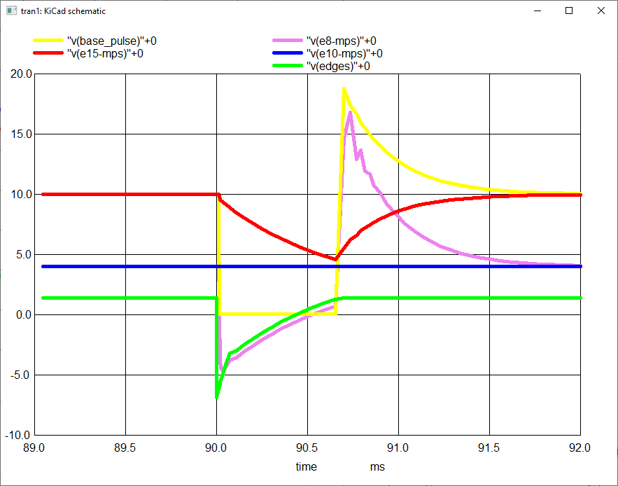
In the following chart the waveforms are not stacked. The voltage on the Y-axis applies to all of the waveforms. This chart was created for 15 inHg of vacuum, e.g. idling.


he green waveform is the edges generated from processing the pulse generator outputs as previously described.
The blue waveform is a constant voltage and comes from the speed compensation and idle mixture circuits.
The yellow waveform is the basic injector pulse.
The falling edge (green) causes current to flow through the primary coil of the MPS (L1, pins 7 and 15, yellow and red on the chart). This creates the initial edge of the injector pulse (yellow).
This then induces a negative voltage in the secondary coil of the MPS (L2, pins 8 and 10, purple and blue on the chart). How negative the voltage on pin 8 goes is dependent on the pressure measured by the MPS.
As the edge waveform (green) rises back up (called decaying) so does the waveform on pin 8 of the MPS (purple).
When the pin 8 waveform reaches a “switch off voltage” (SOV) it causes a change in the circuit resulting in pin 7 of the MPS (yellow) being pulled up, creating the basic pulse.
This rising edge is induced in L2 causing a rising edge on MPS pin 8 (purple).
The longer the voltage takes to decay to the SOV the wider the pulse. Therefore the more negative the voltage due to a lower pressure, the wider the pulse width will be, resulting in a richer mixture.
Here is a chart with the same waveforms stacked for clarity. This is also for 15 inHg of vacuum.

The speed compensation and idle mixture circuits affect the voltage on pin 10 of the MPS (blue). This has the effect of shifting the waveform on pin 8 (purple) to a higher or lower voltage. The result is then taking more or less time for the waveform to reach the SOV and therefore gives a narrower or wider basic injector pulse.
Now lets look at the same waveforms but with 0 inHg of vacuum to compare.

From this point the ECU adjusts the pulse width based on other inputs and finally sends it to the injectors.
Comments are closed