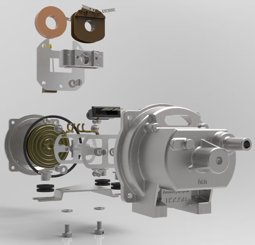
The two coils are wound around a plastic spool with four wire connectors mounted onto the spool. The spool is glued (?) into a metal bracket and the metal bracket is crimped onto a flat frame. This frame is then bolted into the rear half of the case. The coils are covered in a paper ring.
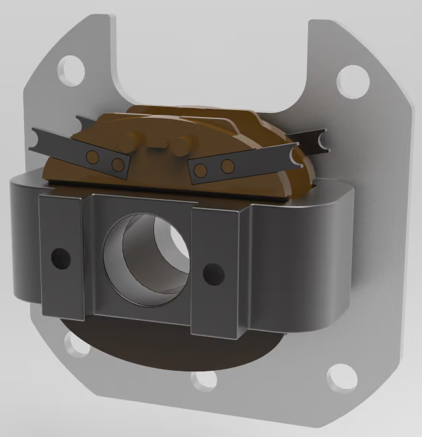
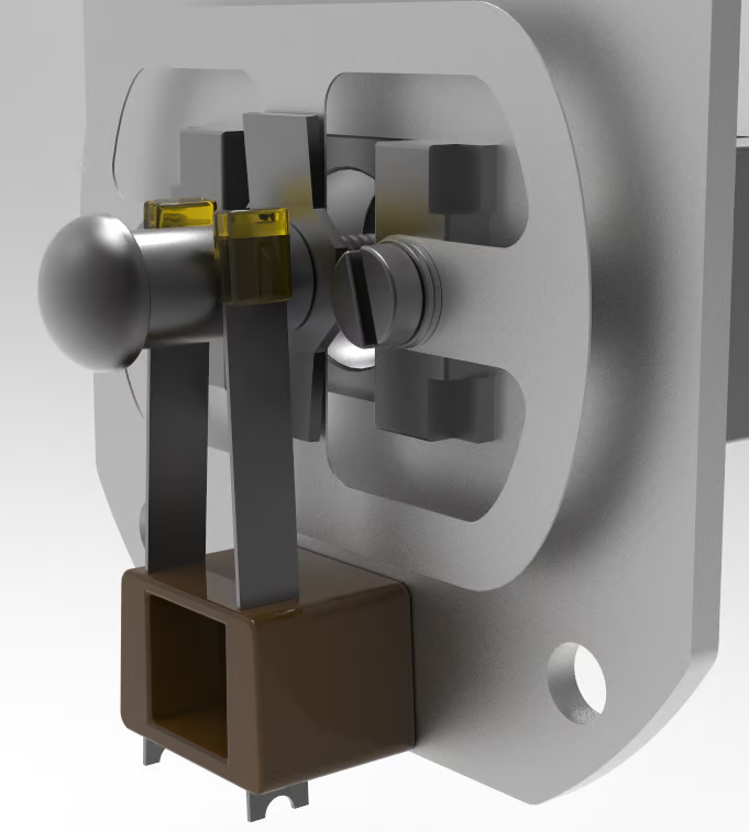
The core is suspended inside the coils so that it can move backwards and forwards. It is held in place at each end by thin, metal guides. Here is the front.
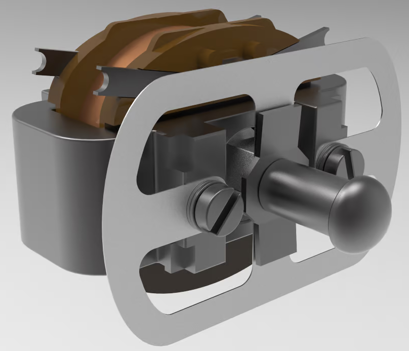
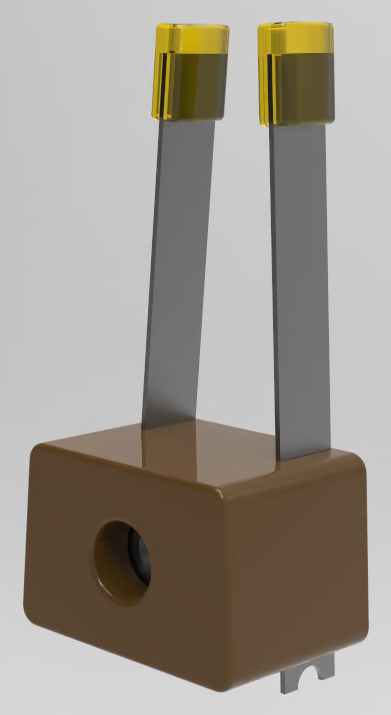
These guides are thin enough that they can flex as the core moves. On the front there is an additional piece that stops the core moving too far backwards. This stop piece has two vertical tabs that come into contact with the mounting frame (not shown).
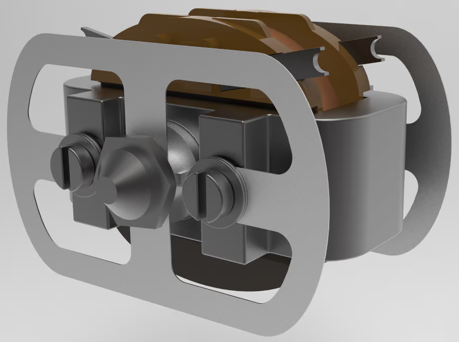
Here is the rear.
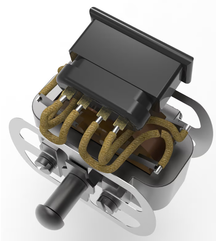
The coils are attached to the connect with four short, braided wires.
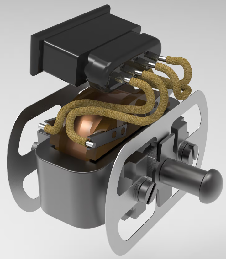
The outer pins 7 and 15 are connected to the coil terminals towards the rear of the MPS.
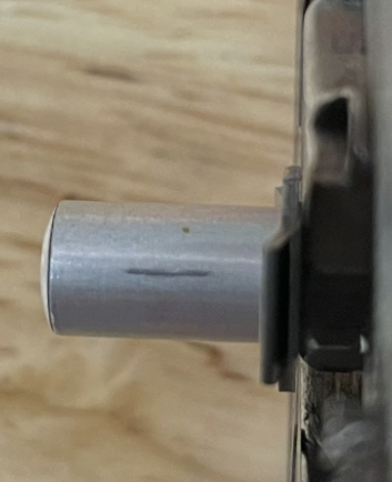
The MPS features a form of guide that presumably keeps the core aligned inside the coils while the vehicle is accelerating and decelerating. The MPS is mounted at 90 degrees to the direction of travel so the guide arms will be in front and behind the core.
These guides rub against the metal part attached to the core as it moves. Here is a photo. I measured 3.5 mm of total travel from the marks.
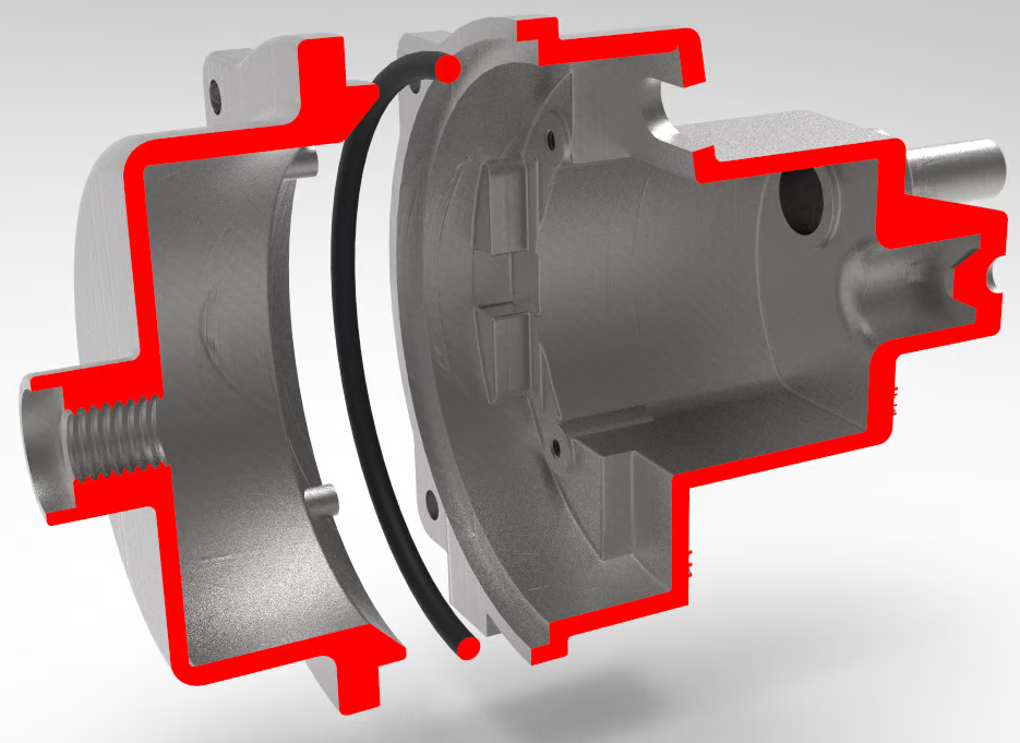
The two case parts are sealed with an o-ring. The rear half of the case is a pretty complex design.
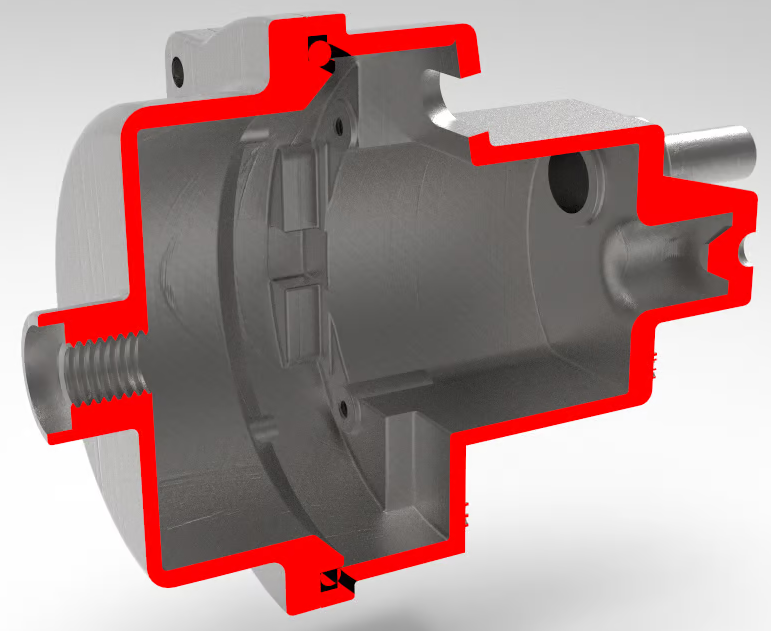
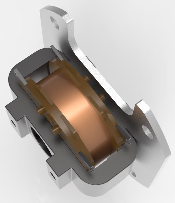
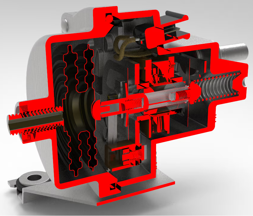
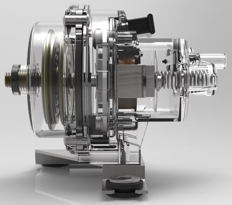
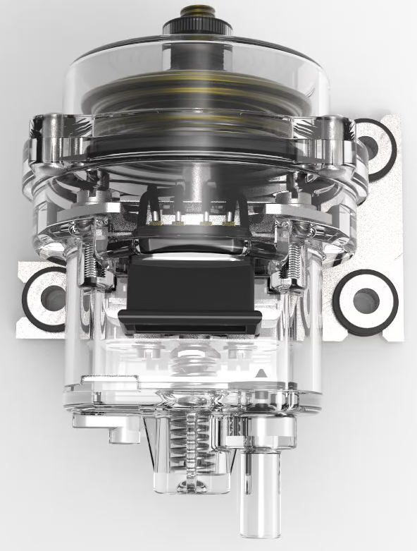
Cutaway of entire device.
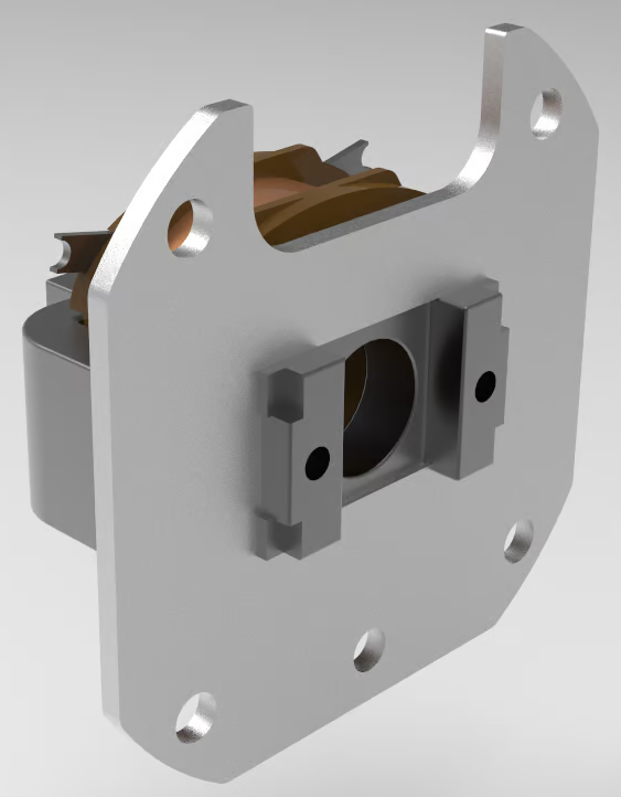
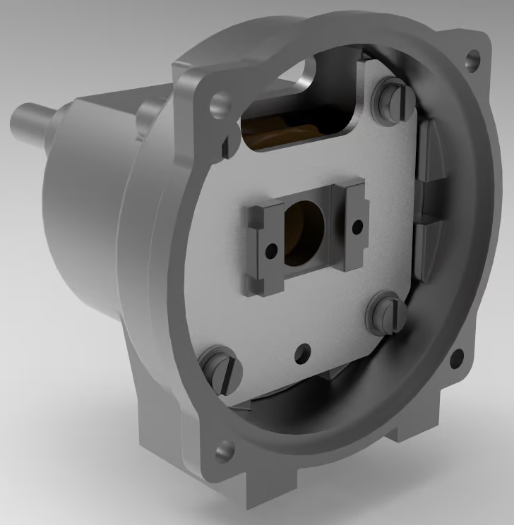
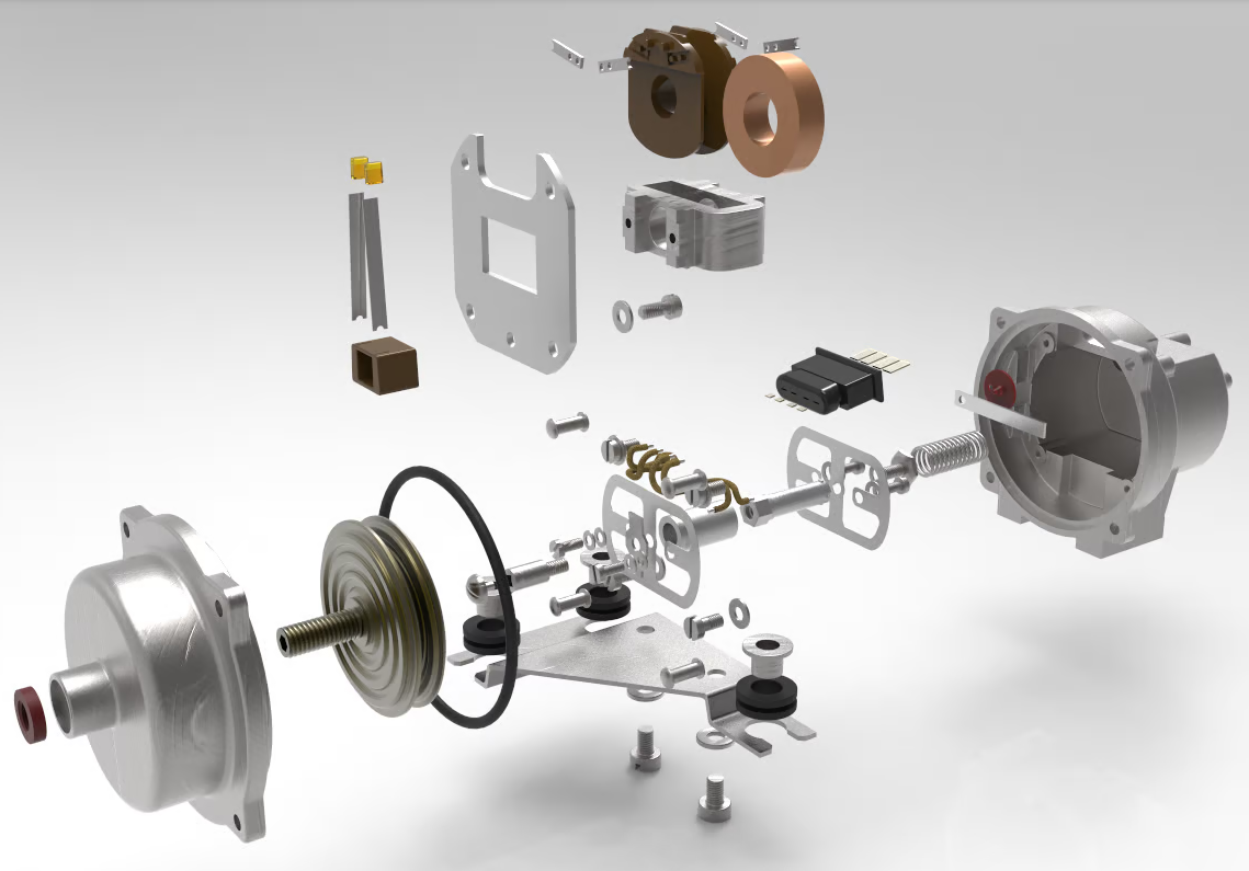
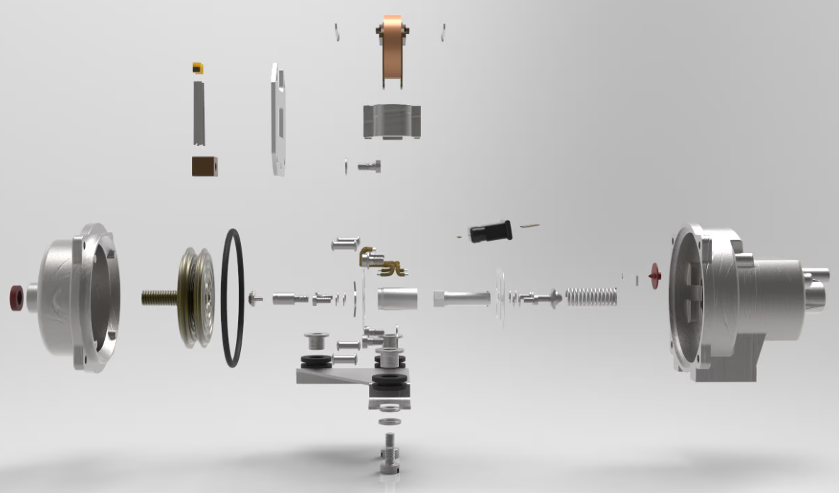
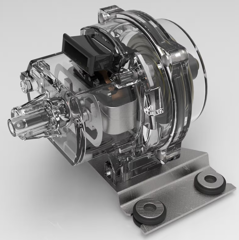
Final renders.
Comments are closed