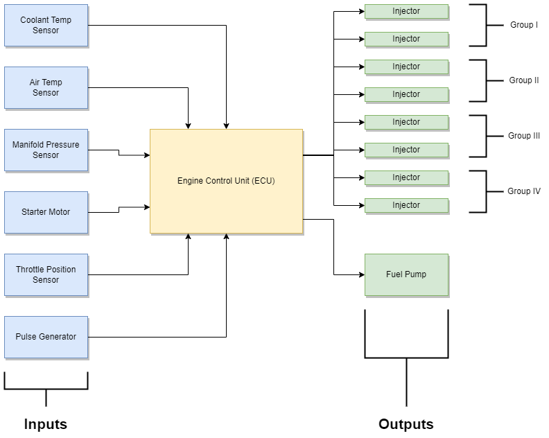
Here is a block diagram showing the components of D-Jetronic (V8 shown).

The Engine Control Unit (ECU) is the brains of the system, taking information from the inputs and controlling the outputs.
The pulse generator is located in the bottom of the distributor and tells the ECU how fast the engine is turning by closing contacts as the distributor rotates.
The manifold pressure sensor (MPS) is a small metal box (located on a fender in the engine bay in Mercedes 450SL and 450SLC) that takes the pressure from the intake manifold and convert that into electrical signals. If the ECU is the brain then the MPS is the heart of the system. With this the ECU can determine the amount of load the engine is under.
The coolant temperature sensor converts the temperature of the engine into an electrical signal to tell the ECU how hot the engine is. The colder the engine the more fuel is injected.
The temperature of the ambient air is reported by the air temperature sensor and this has a relatively small impact on the overall system.
I have included the starter motor on this diagram as an input. I haven’t seen that anywhere else but because it provides a signal to the ECU telling it when the engine is cranking I consider it part of the system. The ECU uses this signal to force the fuel pump to run if the engine rotation speed is not high enough to sustain operation.
The last input is the throttle position sensor (TPS). This tells the ECU if the throttle is at idle, fully open or is increasing. It doesn’t report the position of the throttle. From this the ECU can determine what the driver is requesting.
The outputs are very simple, consisting of only the fuel injectors and turning the fuel pump on or off via a relay. Under normal operation the fuel pump runs continuously so everything the ECU does boils down to one thing – how long to open the injectors for on each rotation of the engine.
It is even simpler than that. The injectors are arranged in groups of two. Each pair of injectors are operated at the same time. One injector in the group will be operated at the correct point in the four-stroke cycle but the other injector isn’t. For that injector the atomized fuel will just sit waiting to be sucked in when the intake valve next opens.
This means that for a V8 engine there are only four injector signals, one for each group.
Note that there is no feedback. The ECU does not monitor the exhaust gases (e.g. via an oxygen sensor). It doesn’t know what the output of the engine actually is. This is called an “open loop system”. That drastically reduces complexity but increases potential inefficiency. The entire system has to be set up and calibrated in order to work correctly.

Comments are closed